Friday 30 April 2010

Tough little mother

 
I was really dubious about these micro-lathes cutting harder metals. I found an M8 Stainless Steel hex head and decided to try and make another T nut to replace the one I got with the SL.
This tough little machine took it all in it's stride! The one supplied to me (it's obviously NOT a Unimat part, it's a shop made replacement), is on the right. The new stainless steel one is on the left.


I'm impressed by this little machine, and I am going to enjoy learning to use it.

By the Lathe for the Lathe

 
One of the things I wanted to do was make parts for the machines that are expensive, hard to come by or out of production. Well I had to do exactly that today.
I had ordered this nice little machine vice for the lathes. I will need it (and a growing list of accessories) if I want to clamp stuff for milling and boring.


Unfortunately it doesn't come supplied with mounting bolts or 'T' nuts. I had two 6mm bolts of the correct length but no 'T' nuts.

'T' nuts are small captive nuts that fit into slots on the machines for clamping and such like. The SL and the Mk4 take (what appears to be) different sizes. Go figure.
I carefully measured the two slots and drew up CAD files for both for future reference. The Mk4 had two T nuts with the toolpost so I carefully measured those with a micrometer and a digital vernier. However, the SL only had a poorly fashioned one that had obviously been made with a file, but since it was working I measured that one too.

I came up with a size that would fit both machines, and made a CAD of three different profiles that would all fit. Now I needed something to make them out of.
Ideally I would have preferred to use some 16mm steel bar, but I would need to mill it and I can't do that without the clamp! Catch 22. I thought I might use some M8 bolts who's heads are the correct distance across that flats but I didn't have any. Flat steel bar would have been another option, but I didn't have that either. I came up with two brass 8M bolts who's heads were about 1mm too big.


I decided that they could be hand finished to get them to fit, I also decided to use the Mk4 to see if my efforts with the chuck had worked.
I faced them both off and turned the shoulder down to the correct diameter and thickness.


The next operation is to centre drill them.


Then drill them out 5mm ready for the M6 thread


I then turned them around in the chuck, parted them off and faced the backs.


I tapped them to 6M and then filed about 1/2 a mill off each face with a hand file. Not pretty but good enough so that I can use the vice and mill the next set!


OK, so it's not much to shout about, most engineering students could do it with their eyes shut, but I'm teaching myself as I go along here, so I'm chuffed.
Here they are in the vice and mounted to the cross slide.

Thursday 29 April 2010

Runout - it's the chuck.

 
The dial gauge and stand arrived today. I had taken the chucks off both the machines in preparation. Measuring the runout at the spindle nose (both external and internal) returned a value on the Metric Dial Gauge that was so small it was unreadable. Certainly less than 0.01mm or 0.0005 inches.
My heart lifted. The new machine is just as accurate as the old one.

Putting the chuck back on the SL and chucking a piece of steel rod gave a readout of around 0.03mm at 2 1/2 inches from the chuck. well within the spec of the machine.
Trying the same thing on the Mk4 gave around 0.08mm, quite a bit worse.

I stripped down the chuck again and gave it another clean up. I ran a brand new 14M x 1mm tap through to clean up the thread which brought out a lot of crud. Poorly cut threads eh? I also went back over the entire chuck with a magnifier. Sure enough there was an index mark! So badly executed that I thought it was a machining mark! I re-assembled the chuck carefully locating the jaws back in the correct order.
Lo and behold, the runout is now identical on both machines! 0.03mm at 2 1/2 inches from the chuck face. COOL!

Next task is to take everything out of the upstairs workshop, pick up the antique bench drill on Sunday and then sort and put everything back so that real work can be done.

One of the things I want to do is try and fit my 'Dremel' rotary tools to the toolpost of the Mk4 and make a punch and die set. I am still waiting for my small machine vice and the milling column for the SL to turn up.

Wednesday 28 April 2010

Tinkering around


Whilst waiting for the dial gauge to arrive I decided to try a few things on the Unimat 4. I tried re-chucking some concentric ground tool steel bar and 'feeling' the runout. You could see it wasn't running true. About 20 thou out.
Then a brainwave. I completely stripped down and meticulously cleaned the chuck and jaws. Re-assembled it with the jaws all going back into their respective slots. Still the same ...... now ....
On the old SL/DB chuck, all the jaws are number stamped and the chuck face is also number stamped and the jaws must be installed in a certain order. This is because on a scroll chuck a flat thread draws all the jaws closed. In order that they all meet in the middle the threads of the jaws are all slightly different patterns..... the previous owner couldn't have been that stupid surely? I had been very careful to reassemble the jaws in the slots they came out of.
I dis-assembled the chuck again. Sure enough the jaws are all number stamped. However, try a I might, I couldn't find any markings of any kind at all on the chuck body.
I re-assembled the chuck moving all the jaws along to the next slot, but in their correct order. Blimey! The runout has dropped down to almost nothing! There is still a slight off centre 'feel' but that was using a piece already cut on the SL. if the two machines are out by about 2 or 3 thou then the combined effect of 5 or 6 thou is about what I'm getting. I'm a lot happier about the machine now. Even if there is a 2 thou runout it will be fine for the stuff I want to do.
I have decided to check both the machines once the dial gauge arrives and see where we are. If required I will fiddle around with the jaws until I am sure they are in the right slots and then mark the back of the chuck somehow.

The 'Unimat' 4

The new, old lathe arrived yesterday. The Unimat 4 is manufactured in the far east, and you can certainly tell the difference. A proper Unimat it aint.
I carefully checked it over last night and it is in good condition for what it is, and will make a good lathe in the end ..... but .... there were a number of problems.
I stripped the entire machine down, and the beds and ways are in good condition with no knocks or scrapes. There are signs of hand lapping or scraping and the ways are well finished. There was swarf and shit everywhere and signs of the original packing grease. This was all removed. It took ages to get all the crud out of the leadscrew though.
The machining of some of the parts is passable at best and not good at worse. What was indescribably stupid were the aftermarket products. A quick change toolpost (QCTP) and a taper-turning top slide. The toolpost had been fitted upside down with a huge washer on the top. At first I couldn't fathom out why, but it then became obvious. The securing bolt that fits the clamp nut was at least 5mm too long for this model. Instead of cutting it back down (as I have now done) the previous owner had driven it into the bed of the cross slide which had deformed it! He had then flipped it over and added the washer to take up the difference. I have checked and this is the bolt supplied with the part. Stupid of the manufacturers.
The taper-turning slide had similar problems. The locating shoulder was about a millimeter to long to fit the hole and the securing bolt was also about 3mm too long. Again I think the previous owner had tried to force it to fit, which is sort of understandable if the product is sold as ready for the machine. I had to grind the shoulder down so that it was a drop in fit and reduce the length of the securing bolt.
Both aftermarket products now fit correctly and the QCTP is really nicely made and will come in very useful.

The deformed part of the cross slide was riding on the un-machined part of the saddle. Useless for any kind of meaningful work. Eventually I will hunt down a replacement, but for now I had to grind back a relief which has left a small hole in the base of the slide. Luckily not anywhere that matters but it may left swarf into the thread. Damn.
All the gibs had to be reset, mostly I fear due to the damage to the slide, but it now runs cleanly and all the threads are clear. The tailstock appears to be fine, so i just gave it a clean up. The keyless chuck as supplied is useless really, it's so long that it reduces the between centre size to about 5 inches. These machines were originally supplied with a 10mm Jacobs chuck, which is missing.
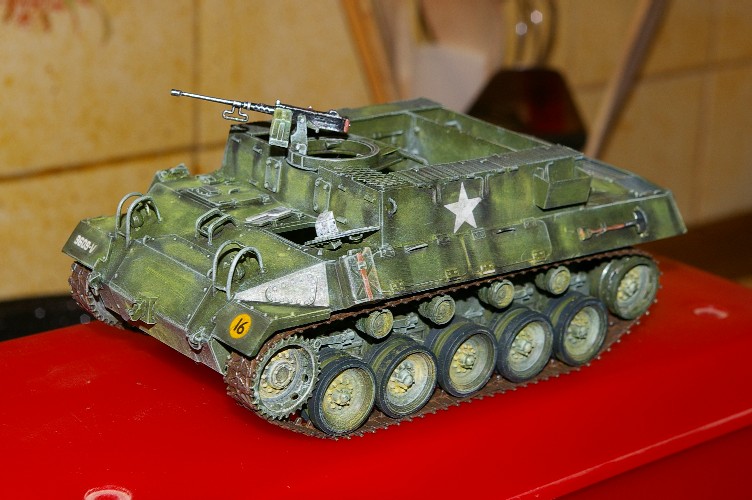
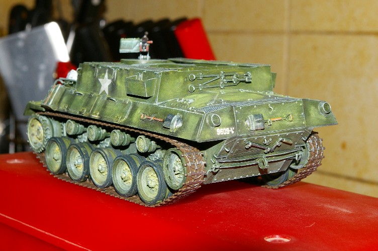
Here's the lathe as it arrived:


Now to the more serious shortcomings of the machine. The motor mount is bloody awful! On the old SL/DB it was a rough, but sturdy alloy casting machined for the location points. This model has a piece of 3mm pressed steel to carry the motor and the idler and it bolts to the back of the headstock. It flexes like crazy. there's a point between the headstock and the motor where you can flex the mounting plate. You can move the back of the motor by 3 or 4mm. Not good.

On a first test cut it was obvious that there are runout problems. About 20thou at 2 inches from the chuck. I have ordered a dial gauge to find out if it's the chuck (hopefully) or a problem with the headstock. I am beginning to wonder if a tool was driven into the original Jacobs chuck and that's why it's missing.
If it's the headstock, then I either have to fit new bearings (a daunting task) or find another headstock. If it's the chuck then getting another won't be a problem.
It could be that the thread of the chuck is as bad as all the other bits so I've ordered a tap so I can run it through.

If I had access to bigger machinery I would try to machine a new motor mounting plate from quality alloy. Anyway I had to adjust all the pulleys since they didn't line up and I've ordered a new set of belts too.

Why go to all this trouble? Well the machine was CHEAP even for this model and it has much better bed clearance than the SL. Even with riser blocks.
If I spend another £100.00 getting it all working then it will still be cheaper than a second SL or a Mk3.

Tuesday 27 April 2010

My micro workshop


My plan is coming to fruition! I managed to order the milling post for the old Unimat from the USA. Even with shipping it was 25% cheaper than I can get one here in the UK. Madness.
I bought an old (vintage) Grayson model engineers pillar drill for a song. It will almost certainly need a bit of work to get it back into shape, but I'm in no rush.
The second Unimat proved to be a real problem, but I found a Mk4 for a good price. These have a slightly underrated reputation being a far eastern (not Austrian) manufactured unit, but it's a late model and should be good for my sort of work. Also many more accessories are readily available for the Mk3 and Mk4, as opposed to the SL-1000 where parts come up infrequently.

With the compressor I already have, a small engineers vice and possibly a small bench bandsaw, I will have all the equipment for my micro workshop. I will then start looking to add all the accessories to the two lathes. One advantage of this is that the SL milling head only needs a support block to work over the Mk4 table, so a lot more work can be done.

I await delivery of all three machine parts, pictures will then follow.

I've done more work on the M114, and I now have 10 cast wheels waiting for machining. I'll use them as a test of the new Mk4 when it arrives and report back. Meanwhile here are the images for the work I've done.


Six disks make up each rear idler.


Drilled and cut ready for assembly


The two rear idlers ready for paint.


Selection of 'likely' candidates from scrap to make the pattern match for the road wheels.


The final parts selction for the pattern match.


Assembly work started.


Hub nearly complete, it will need some Milliput to finish


Assembly work completed now for the Milliput ....


The completed pattern match, now they will be cast in resin and machined.


A completed test wheel, this one was rejected since the casting has lost some edge detail on the left. It will be used for test fitting and ground clearance.

Sunday 18 April 2010

Scratchbuilt M114 APC

I decided to try and buy a second Unimat to use as a drill / milling machine. Didn't quite go according to plan. I sold some old radio gear on ebay that I haven't used for a couple of years. I managed to raise £250.00 for my new machine tool. At the time there were 4 Unimat SL lathes on ebay, all a bit more than I wanted to spend, so I hunted around and found one on Homeworkshop for the right price. I emailed the guy and he said it was still available, so I asked him to mail over his paypal account details so I could pay him........ heard nothing for two days. Mailed him back only to be told that it had been sold! To$$er!
By that time all the ones on ebay had gone, bugga. So I've put a couple more things on ebay to raise a few more quid while I wait for another one to come up.

In the meantime the drawings from George Bradford in Canada arrived. Fantastic! Along with a load of images and reference material I have enough to start work on 5 vehicles.
I chose to begin with an M114 APC since I had tried to build one 20 years ago from an article in Millitary Modeller, but was defeated by the wheels and tracks. I have more time, a little more experience and some better tools now.
The M114 is easy and very difficult all at once. The main chassis is all straight edges and no compound curves or difficult angles. However, the wheels and tracks seem to e unique to this vehicle and therefore very fiddly and tedious. We'll see how I get on over the coming months eh?

Here the main side panels have been cut from Plasticard using the 'score and snap' method, George's excellent drawing can be seen on the left. His is for an M114A1, but I will be building the straight M114. The differences are minor.
As an aside, Blogspot's image uploader needs revision, it won't put images at the insertion point! It keeps putting them at the top of the blog which is a pain, unless I'm doing something stupid?


I've added the base of the chassis and the front and rear panels. A couple of bracing pieces have been included to keep everything square.


The simple main body of the chassis completed. I decided not to cut out the hatches and have to build an interior. Mostly because I didn't want the hassle knowing what was to come with the wheels and tracks.


I've started to add surface details here, the hatch covers, fuel filler caps, lifting hooks and vent grills. All from bits of plasticard or cast resin. A first template for the wheels can be seen on the right but I don't know if I will use it or not yet.


Another view of the first detail stage. The 'Mayflower' in the background is awaiting rigging and sails to complete. Another really fiddly job that I'm putting off for a bit.


Finally a couple of images of the current state of play. There are a few more details to add to the main chassis before it's complete and I start on the wheels and tracks.

Saturday 10 April 2010

Where did all the years go?


This week I decided to have a clear out of stuff to put on ebay. Partly to try and fund stuff for the workshop.
One of the things I dug out of the loft was my old Akai 4000DS Mk2 reel to reel tape deck. I ran a couple of tapes through it and ended up listening for HOURs! Such a rich, warm sound from this bit of 1970s Hi-Fi. Seems that music was more of a ritual back then, no remotes, no digital, just lose yourself in it all. Somehow CD, Mini-Disk, DVD and MP3 just don't have the same appeal?

I was intending to raise enough to buy the missing bits for the Unimat, but if I raise enough I might buy another one with all the bits and set that one up for milling and drilling so the bits are interchangeable. We'll see ........

Somehow I hope the Akai doesn't sell, sounds silly but there you go.

Wednesday 7 April 2010

Unemployed again after three years!

Well, I can't believe that it has been 3 years since I posted on here! I was just too busy.
The project I ran was really excellent and I was using up all the hours under the sun. However, due to funding being cut I now find myself without gainful employment once again.
Since I have time on my hands I've been doing a few thing that have sat on the back burner for too long.

One of those was to do some scale model making and scratchbuilding. I had a few kits and ideas floating around. One was the
construction of some AFVs that aren't available as kits, or were to expensive to buy. I started with an M39 APC, results below:


In addition I have written off to George Bradford in Canada for some scale drawings for a few more scratchbuilt vehicles. George has an excellent range of 1/35th scale plans for a very reasonable price.

In order to make model parts my wife bought me a watchmakers / modellers lathe a couple of years back. I haven't really used it at all, but I thought it would be good to try and learn how to use it! Here's how it looked the day we got it home, it's a Unimat SL-1000/DB-200:


I have already realised that there are a lot of the original parts missing! I have bought some nice indexing cutting tools, but the lack of the milling attachment is very annoying although we only paid a small amount for the lathe.

The next thing is to sell some old radio stuff on e-bay and see if I can manage to get some of the missing parts for the lathe.